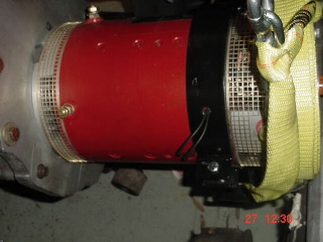
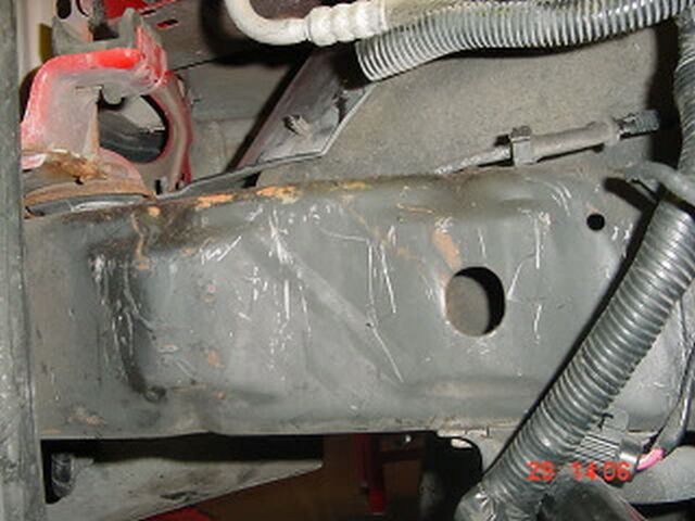
Appear though it encompasses the shaft of the WarP. Walt 10/20
walt 10/20
Walt,
I will annotate your note with answers.
----- Original Message -----
Sent: Sunday, October 19, 2008 2:34 PM
Subject: Some more questions
Let me start by stating my appreciating your
support. I have started
a cross index, subject matter vs date in
the diary for my quick
reference. I dislike attempting to remember
where is saw information,
thumbing through page after
page.
Good
work!
I went to Lowes yesterday and
purchased the conduit material save on
item you have listed. The list
indicates two couplings, one Sch40 and
one std PVC. I purchased on as
I was unable to see where the second
one is used. Let's see if I have
the correct order. The female adapter
fits down through the hole in
the bed, followed by one 45º then a 90º,
then the straight long piece,
the std. coupling, then by a 45º and a
90º up in the front motor
compartment. So where is the second coupling
fit it?
I guess I am not sure about the second
adapter. I may have been considering it for the end of the conduit under
the hood. When I made the parts list, I didn't consider how I used the
parts, just what I purchased.
The key thing to remember here is the a 45 and a
90 are used on each end, and you have to shorten both 90 degree
pieces. This whole thing is a force fit. There may be some trial and
error.
I looked around the garage and found two pieces
of conduit material. I have attached a picture of them.

IMG_4065.JPG
I believe
the larger piece was cut from the front 90 degree piece on the narrow end of the
curve (2 inches). The short piece comes from the wide end of
the rear 90 degree piece (7/8 inch). This is a pretty good guess, but
it is a guess. Have them do some measurments of their own to verify.
If it doesn't work the first time, do it over.
Curtis controller/heat sink - is there a paste
req'd between the
surfaces?
Yes, heat sink compound is absolutely
required.
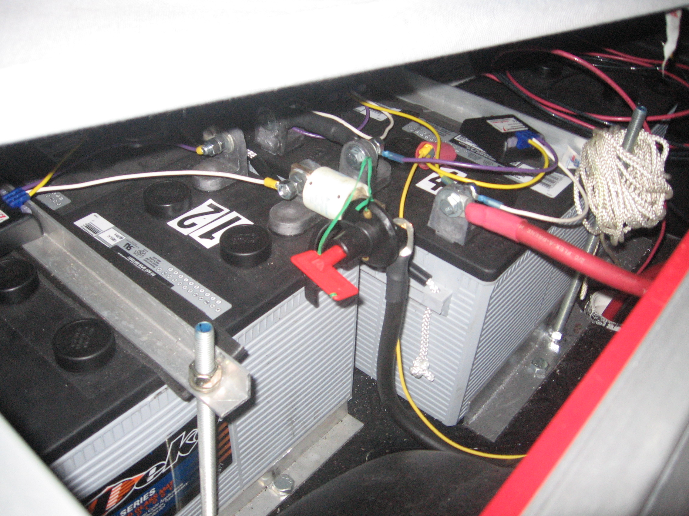
Battery connections - cable lug to btry post - 10/17/07 use
1-1/4"
stainless bolts, still a good size? Use flat & lock
washers? Are the
connections assembled dry?
Assuming your batteries have the L terminal with 3/8 inch
hole, you need 24 1-1/4" 5/16" bolts and 48 nuts. A flat washer
should go between the bolt head and the lead post. the lug side of the
post should be coated with noalox. The lug should be slid onto the
bolt. A flat washer should be placed on next followed by a Belleville
washer (convex side out, concave side against the flat washer). The flat
washers protect the soft metal surfaces of the post and the lug from the hard
edges of the bolt head on the one side and the bellville washer on the
other.
275px-Belleville_washer.JPG
The bellville washer provides equalized pressure all around the
flat washer, unlike a split lock washer. The Noalox is a conductive
lubricant that enhances conductiveity and prevents oxidation of the conductive
surfaces. Bolts are tightend to a
Terminal Torque of 60
in./lbs.
NoAlox Joint Compound
http://www.evsource.com/tls_cabling_tools.phpBattery
rack - front - by chance do you have any sketches of this
indicating
stock and lengths? 12/19/07 entry - "the steel bowed in the
center
leaving the center btry loose" - this is the steel plate piece
shown
in the 12/12/07 pic under the cow mat. Would a thicker piece of
stock
work better or an angle bolted/welded underneath?
Monte has a copy of the front
battery rack drawing. I gave it to him while I was there. If you
need another let me know. It is quite large. In addition, there are
pictures of the rack on October 4th and October 15tth.
This is what I said: "In the front
rack is made of steel. There is a flat piece of steel under
the mat to
support it."
When I ssaid "support it" I mean the mat not the steel. The purpose of the 1/8" x 3" x 26" flat steel is to
prevent the mat from pushing through the large hole in the steel frame. It
is not welded because it was a last minute addition. It is working fine,
pressed in place by the weight of the batterries on the mat. It certainly
could be weled. I would put it just where I have it, not underneath.
http://www.evprogress.org/99%20Ranger_files/image180.jpg
It creates a perfectly flat surface because it is the same thickness as the
angle at the edges,.
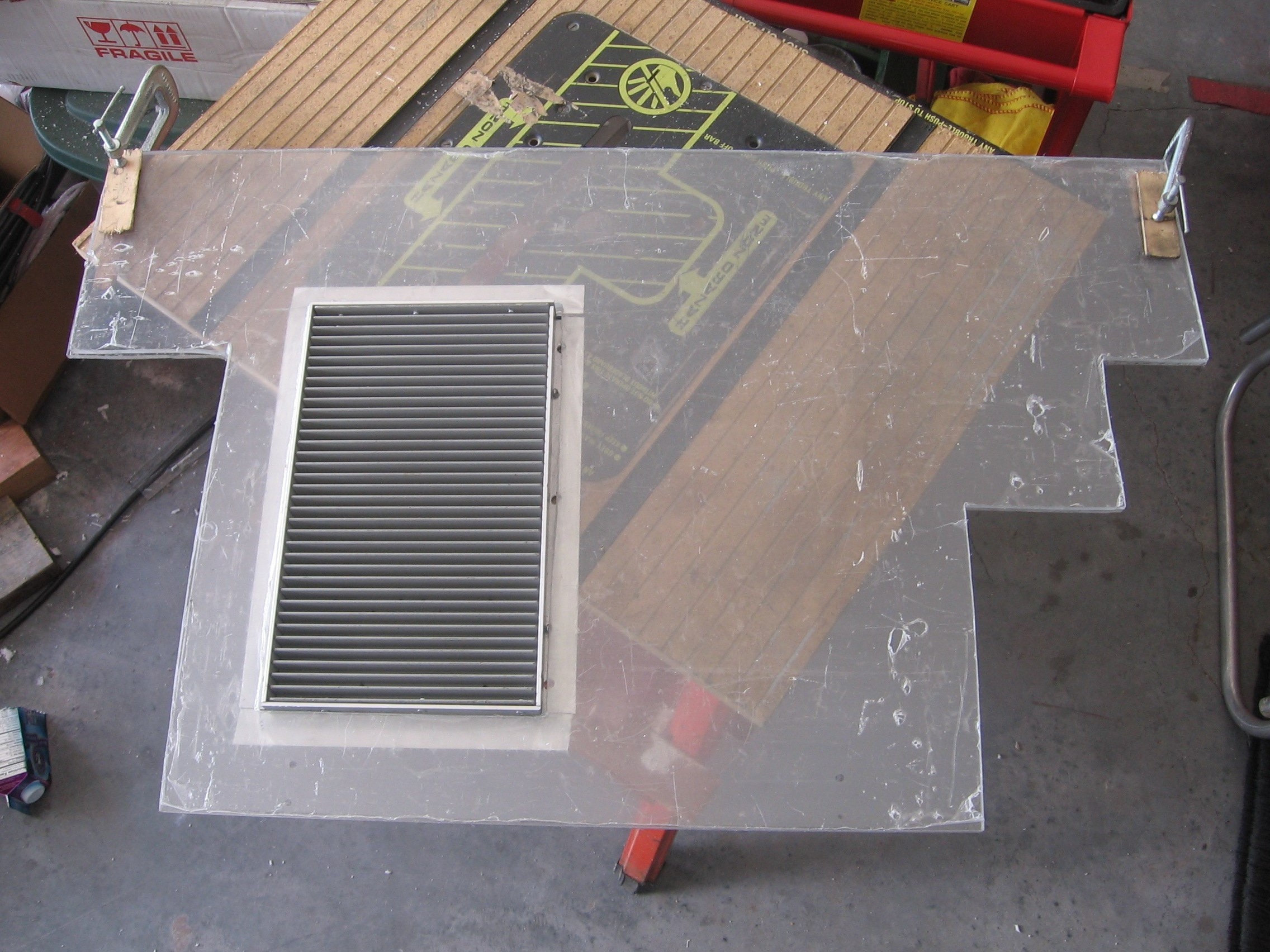
Table top - two pieces of acrylic - what
thickness did you use, saw
0.125" ? Use any adhesive to keep the
two sheets together? That is
before adding the metal edges.
10/27-28/07 pics shows mounting of heat
sink prior to edge
mat'l.
I just measured the material I used.with
a caliper. It is .23 inches thick, nominally .25 or 1/4 inch. I used
no adhesive. Two pieces would be about a half inch. The pictures are trial
fit pictures, not final assembly. The final insertion of the acrylic into
the frame was on December 3. Remember the acrylic must be removed for
welding. All photos prior to December 3rd are trial fits. In many of
the pictures the components are simply lying in place and not
bolted.
11/19/07 - Remounting of hinges - use of inner tube -
don't understand
their placement. Is this between the table top frame
and the hinge?
10/30/07 pic seems to indicate hinge is on top of
acrylic with bolts/
screws/rivets going through to metal. Is metal angle
stock or flat?
See pic 11/2/07 - What is that triangular piece that
appears to be in
the middle of the angle mounted to the fire wall, it
has a hole in the
middle?
You have to ignore some of this. I
wanted the table aluminum to be above chassis ground. All my attempts
failed. In the end I removed all the rubber insulating
material.
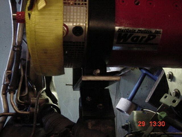
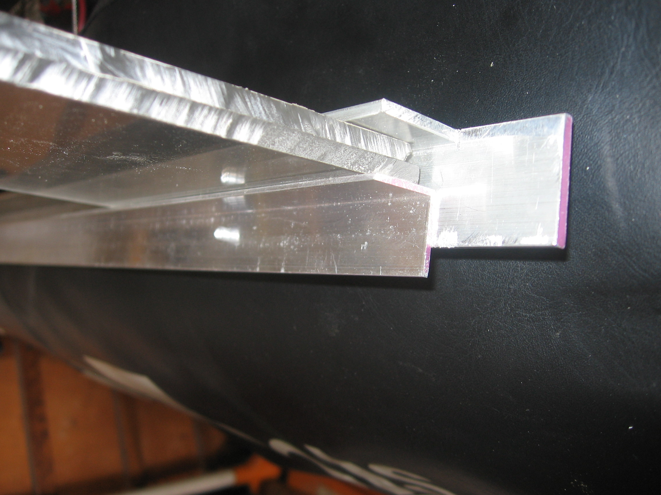
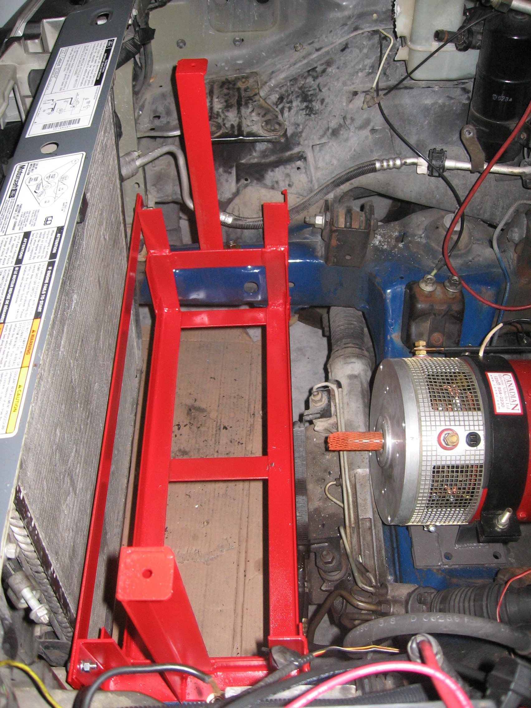
The 10/20 picture is a good one because
it is unclutered by components. You see three pieces of
aluminum stock. The one closest to the viewer is flat. I have
attached a picture that might help.

Frame rear.jpg
The little triange with the round nose is
not essential. Its purpose is to provide a resting place for the table top
during installation. Remember I am working alone. It supports the
table top untill the pins are inserted into the hinges.
Cheers,
Al Lococo
I went to Lowes yesterday and purchased the conduit material save on
item you have listed. The list indicates two couplings, one Sch40 and
one std PVC. I purchased on as I was unable to see where the second
one is used. Let's see if I have the correct order. The female adapter
fits down through the hole in the bed, followed by one 45º then a 90º,
then the straight long piece, the std. coupling, then by a 45º and a
90º up in the front motor compartment. So where is the second coupling
fit it?
I guess I am not sure about the second adapter. I may have been considering it for the end of the conduit under the hood. When I made the parts list, I didn't consider how I used the parts, just what I purchased.
The key thing to remember here is the a 45 and a 90 are used on each end, and you have to shorten both 90 degree pieces. This whole thing is a force fit. There may be some trial and error.
I looked around the garage and found two pieces of conduit material. I have attached a picture of them. I believe the larger piece was cut from the front 90 degree piece on the narrow end of the curve (2 inches"). The short piece comes from the wide end of the rear 90 degree piece (7/8 inch). This is a pretty good guess, but it is a guess. Have them do some measurments of their own to verify. If it doesn't work the first time, do it over.
Curtis controller/heat sink - is there a paste req'd between the
surfaces?
Yes, heat sink compound is absolutely required.
http://shop.willyselectronics.com/browse.cfm/4,7782.html
Battery connections - cable lug to btry post - 10/17/07 use 1-1/4"
stainless bolts, still a good size? Use flat & lock washers? Are the
connections assembled dry?
Assuming your batteries have the L terminal with 3/8 inch hole, you need 24 1-1/4" 5/16" bolts and 48 nuts. A flat washer should go between the bolt head and the lead post. the lug side of the post should be coated with noalox. The lug should be slid onto the bolt. A flat washer should be placed on next followed by a Belleville washer (convex side out, concave side against the flat washer). The flat washers protect the soft metal surfaces of the post and the lug from the hard edges of the bolt head on the one side and the bellville washer on the other. The bellville washer provides equalized pressure all around the flat washer, unlike a split lock washer. The Noalox is a conductive lubricant that enhances conductiveity and prevents oxidation of the conductive surfaces. Bolts are tightend to a Terminal Torque of 60 in./lbs.
NoAlox Joint Compound
http://www.evsource.com/tls_cabling_tools.php
Battery rack - front - by chance do you have any sketches of this
indicating stock and lengths? 12/19/07 entry - "the steel bowed in the
center leaving the center btry loose" - this is the steel plate piece
shown in the 12/12/07 pic under the cow mat. Would a thicker piece of
stock work better or an angle bolted/welded underneath?
Monte has a copy of the front battery rack drawing. I gave it to him while I was there. If you need another let me know. It is quite large. In addition, there are pictures of the rack on October 4th and October 15tth.
This is what I said: "In the front rack is made of steel. There is a flat piece of steel under
the mat to support it." When I ssaid "support it" I mean the mat not the steel. The purpose of the 1/8" x 3" x 26" flat steel is to prevent the mat from pushing through the large hole in the steel frame. It is not welded because it was a last minute addition. It is working fine, pressed in place by the weight of the batterries on the mat. It certainly could be weled. I would put it just where I have it, not underneath. It creates a perfectly flat surface because it is the same thickness as the angle at the edges,.
Table top - two pieces of acrylic - what thickness did you use, saw
0.125" ? Use any adhesive to keep the two sheets together? That is
before adding the metal edges. 10/27-28/07 pics shows mounting of heat
sink prior to edge mat'l.
I just measured the material I used.with a caliper. It is .23 inches thick, nominally .25 or 1/4 inch. I used no adhesive. Two pieces would be about a half inch. The pictures are trial fit pictures, not final assembly. The final insertion of the acrylic into the frame was on December 3. Remember the acrylic must be removed for welding. All photos prior to December 3rd are trial fits. In many of the pictures the components are simply lying in place and not bolted.
11/19/07 - Remounting of hinges - use of inner tube - don't understand
their placement. Is this between the table top frame and the hinge?
10/30/07 pic seems to indicate hinge is on top of acrylic with bolts/
screws/rivets going through to metal. Is metal angle stock or flat?
See pic 11/2/07 - What is that triangular piece that appears to be in
the middle of the angle mounted to the fire wall, it has a hole in the
middle?
You have to ignore some of this. I wanted the table aluminum to be above chassis ground. All my attempts failed. In the end I removed all the rubber insulating material.
The 10/20 picture is a good one because it is unclutered by components. You see three pieces of aluminumstock. The one closest to the viewer is flat. I have attached a picture that might help.
The little triange with the round nose is not essential. Its purpose is to provide a resting place for the table top during installation. Remember I am working alone. It supports the table top untill the pins are inserted into the hinges.
Walt 10/19
Let me start by stating my appreciating your support. I have started
a cross index, subject matter vs date in the diary for my quick
reference. I dislike attempting to remember where is saw information,
thumbing through page after page.
I went to Lowes yesterday and purchased the conduit material save on
item you have listed. The list indicates two couplings, one Sch40 and
one std PVC. I purchased on as I was unable to see where the second
one is used. Let's see if I have the correct order. The female adapter
fits down through the hole in the bed, followed by one 45º then a 90º,
then the straight long piece, the std. coupling, then by a 45º and a
90º up in the front motor compartment. So where is the second coupling
fit it?
Curtis controller/heat sink - is there a paste req'd between the
surfaces?
Battery connections - cable lug to btry post - 10/17/07 use 1-1/4"
stainless bolts, still a good size? Use flat & lock washers? Are the
connections assembled dry?
Battery rack - front - by chance do you have any sketches of this
indicating stock and lengths? 12/19/07 entry - "the steel bowed in the
center leaving the center btry loose" - this is the steel plate piece
shown in the 12/12/07 pic under the cow mat. Would a thicker piece of
stock work better or an angle bolted/welded underneath?
Table top - two pieces of acrylic - what thickness did you use, saw
0.125" ? Use any adhesive to keep the two sheets together? That is
before adding the metal edges. 10/27-28/07 pics shows mounting of heat
sink prior to edge mat'l.
11/19/07 - Remounting of hinges - use of inner tube - don't understand
their placement. Is this between the table top frame and the hinge?
10/30/07 pic seems to indicate hinge is on top of acrylic with bolts/
screws/rivets going through to metal. Is metal angle stock or flat?
See pic 11/2/07 - What is that triangular piece that appears to be in
the middle of the angle mounted to the fire wall, it has a hole in the
middle?
Walt 10/19
Walt,
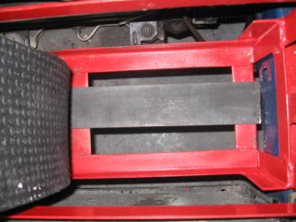
The picture you are looking at is a product purchased at Walmart for $19.00.
It is used as a mat under a tread mill. I cut it up and used it to cover
the battery terminals.
Tractor Supply is a chain of farm supply stores. They have a product called
a stall mat which is about 3/4" thick which I used under the batteries. It
is much thicker than what is pictured in the photo you have sent me.
In the front, the rack is made of steel. There is a flat piece of steel under
the mat to support it. The batteries are place on top of it. It is cut and
placed so that the battery handles hang over the edge of the mat.
In the rear, the mat is under both the batteries and the hold down aluminum
frame.
Cheers,
Al Lococo
Your pic P1010034.jpg, showing
the "rubber" mat, is that the same as the"stall mat" from Farm
Supply? If so from the 4 X 6 piece?
Walt 10/17
In November we should be really running. The
adapter assembly s/b in by the end of this month. Controller is 4
weeks from now, or the week on 11/10.
Walt 11/17
Waalt,
I ordered. 20 feet of red 2/0 cable and 30 feet of black 2/0 cable with not
a lot left over when done.
Cheers,
Al Lococo
I have ordered all of the big items.
Don't have delivery dates on them. Anticipate that the adapter will be
in by the end of next week at the earliest, he has cashed the check,
by the end of the month the latest. Anticipate that following that,
the pace should pick up.
If Olive's health picks up we are heading north for Thanksgiving to
Grand Rapids for a week. I would anticipate we would have the major
part of the work completed by then. That said, hoping for no major
delays in part acquisition.
I will get a heads up today. Walt 10/17
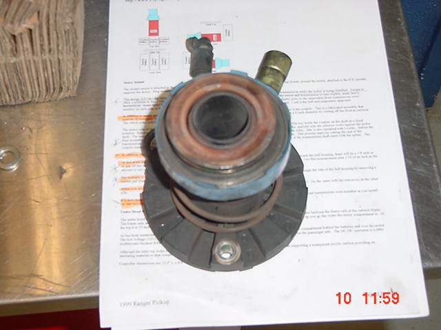
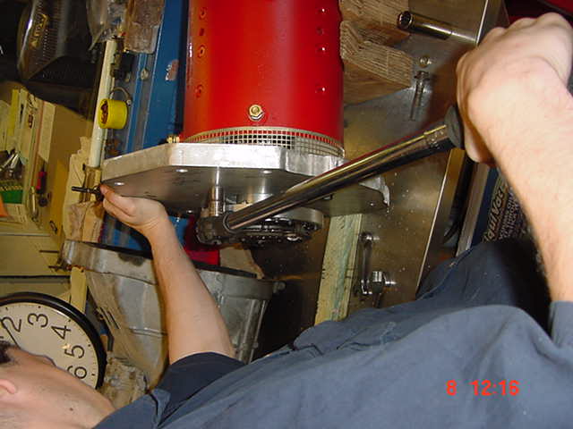
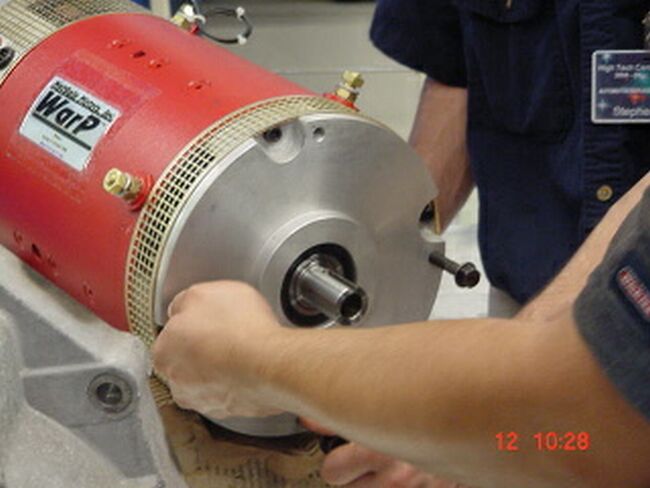
Walt,
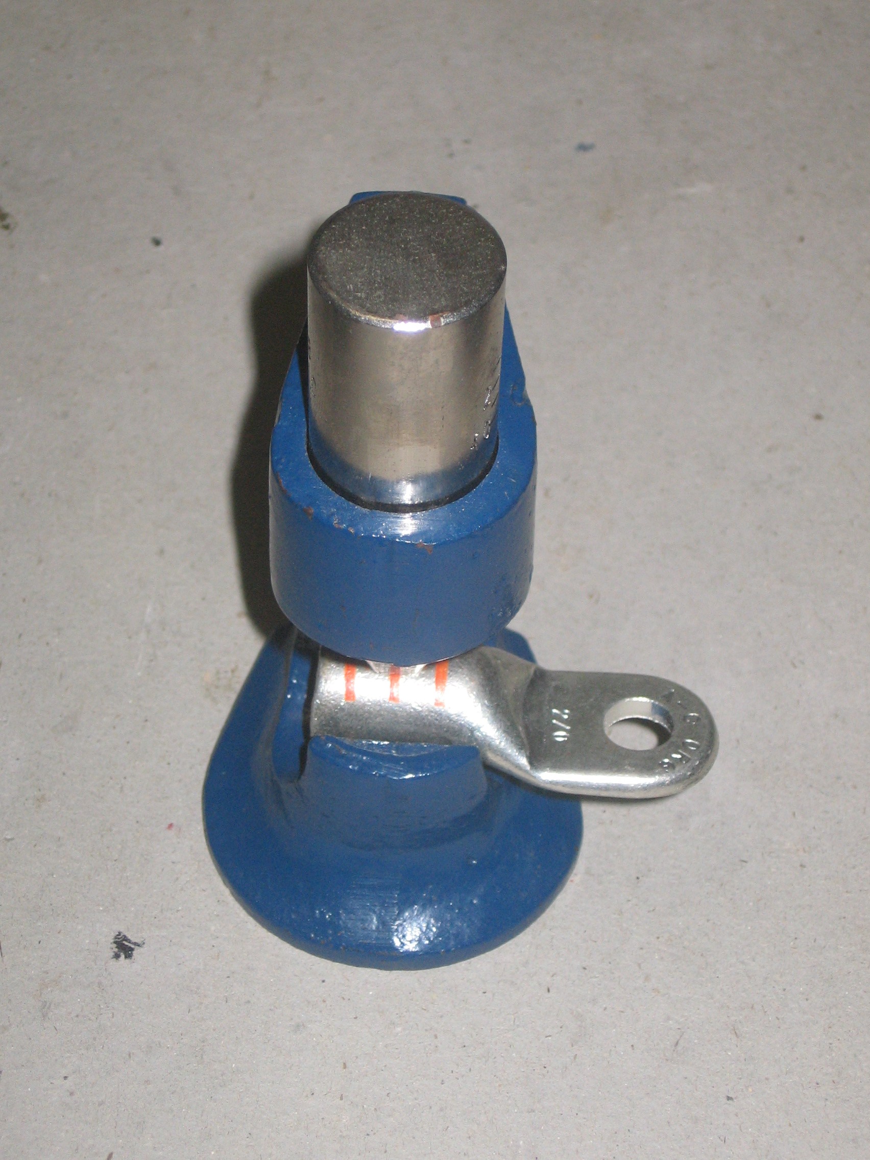
That's great. If I were doing this again, I think I would try to get the pilot shaft inside the motor shaft. It makes the measurements more critical, but would help to minimize vibration. I think I would put a small amount of GE Silicone at the bottom of the motor shaft hole before inserting the transmission pilot shaft. This might help dampen vibration from the loose fitting metal on metal surfaces and tighten things up a bit. It should work since both shafts always turn together.
Cheers,
Al Lococo
I measured the pilot shaft from the transmission and it appears to
0.60" in diameter. I was getting 0.59 more often than 0.60.
Approximately 0.75" deep up to the beginning of the spline, (not the
most accurate measurement). According to NetGain's drwg (see below)
of the WarP 9", the inside diameter of the shaft is 0.689/0.687. So,
there appears to be an opportunity to insert the pilot shaft into the
motor shaft recess as you have suggested.

Photo of the Serial number.

The only item to report is on Friday 10/3, they removed the gas tank
and the clutch disk. The clutch disk was sent via UPS to Wayne
Alexander,Walton, KS, this morning. Should arrive there on Friday,
10/10/08. Wayne estimated 2 to 3 weeks turnaround.
I will be ordering much of the balance of equipment this week. There
is a Farm Supply store not too far from Monte's school.
Walt 10/6
Walt,
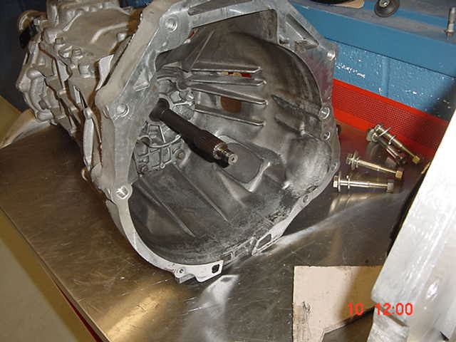
Nice picture. Step 5 affectss things related, but not shown. The master
cylinder is operated by a rod that goes through the fire wall from the pedal
to the master cylinder.
Remove hydraulic line between master cylinder and the clutch slave cylinder
from the clutch slave cylinder, (Number five in your drawing, tricky) first.
There is a special tool for this. Push the white plastic cylinder twards
the transmission while pulling on the hydraulic line. Not easy, but it can
be done. If you have to you can cut the hydraulic line.
Be careful not to disturb the speedometer wires. Remove slave cylinder
assembly from transmission drive shaft.
Cheers,
Al Lococo
In that the instructions must be given to the crew, want to be sure it
is correct. Following all of this will be the instructions that you
sent yesterday for installing the modified clutch disk, etc.
Walt. 10/5
From the EXISTING clutch assembly:
1) Remove and discard flywheel (#1 in drwg)
2) Remove and SAVE clutch disk (#3 in drwg)
3) Remove and discard clutch pressure plate (#4 in drwg)
4) Remove and discard clutch slave cylinder, clutch release hub &
bearing (#5 in drwg)
Walt 10/4

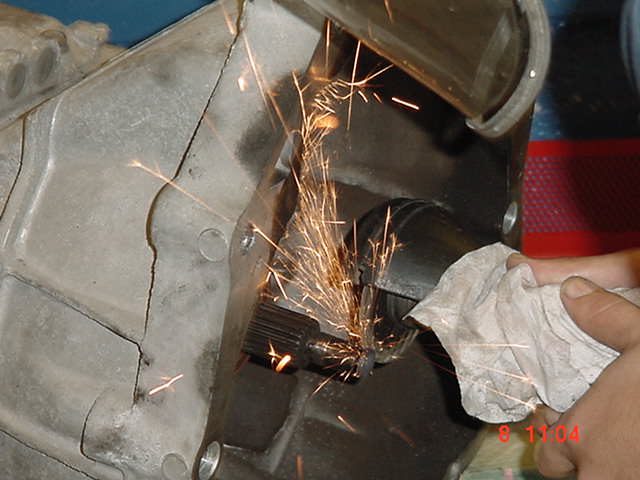
Walt,
In the ICE, the flange on the crank attaches to the flywheel . The clutch
asembly is attached to the opposite side of the flywheel. This assembly
contains the clutch disk which has the friction sufrace and at the center
the female spline which slide on and off the male spline on the Because the
clutch disk moves on and off the the male spline on the transmission shaft,
the pilot shaft at the motor side of the male transmission spline keeps the
transmission shaft from wobbling when the clutch is disengaged.
Now all of this is prologue and if it is confusing it can be ignored.

The clutch disk is retained.
They flywhell with its pilot surfase is discarded. As is all the rest of
the clutch assembly with the exception of the clutch disk because, it has
the female spine we are going to need.
Now we don't need the friction surface on the clutch disk because it will be
engaged full time. It nolonger slides off when you depress the clutch,
because we remove everything related to the clutch except the cluch disk.
The remaining problem is how to attach the center portion of the clutch disk
to the electric motor? Tjis what the coupler does. It has a keyed hole on
one side that slides onto the electric motor shaft which is also keyed. On
the other side we bolt the clutch disk with the friction surfaces removed.
this two part assembly has a keyed hole on one side and a female sline on
the other.
The coupler, a two part assembly could be machined with a keyed hole on one
side and a female spline on the other and machine from steel. This would
eliminate the need for the clutch disk.
So the design using the clutch disk is an expediant. It simplifies the
machining of the coupler. The use of the clutch disk may be confusing
because therre is no longer a clutch. The clutch disk is always engauged
minimising the need for a pilot shaft and a pilot bearing. The pilot shaft
is now the male spline on the transmission shaft and the pilot bearing
surface is the female spline on the one time clutch, now coupleer assembly.
The two are alwys engaged turning or together, no slipage as when the ICE
turns but the transmission shaft is motionless or they are static together.
Cheers,
Al Lococo
CLARIFICATION: you use the words 'The clutch plate'' do you mean the
"clutch disc? In the diagram #3 is CLUTCH DISC; #4 is CLUTCH PRESSURE
PLATE. hen do you mean to reattach the CLUTCH DISC to the CLUTCH
PRESSURE PLATE?
Walt 10/4
Just reread your entry on this, let's see if I now understand. In your
section entitled "motor mount", you stat "this a fabricated assembly
that consists of two parts, the coupler and the spline from the clutch
friction plate. The cllutch plate is cut down to about a 9-inch
diameter by cutting off the friction surfaces. The clutch plate with
the spline at the center is bolted to the custom machined coupler." I
see now as the blind man said! It just sank in what all of that meant!
As they used to say at the UofIll., rhet as writ. Interpreted means
read it until you understand. Please confirm that I am now on the
correct track. I studying the clutch assembly now, having the shop
manual helps. Walt 10/4
on the connection of the motor to the transmission. I don't understand
why the clutch disk is kept in operation. I thought that the coupler
would be attached to the motor shaft on one end and the other to the
shat in the transmission. As I interpret the drawings, there is a
transmission input shaft pilot bearing in the flywheel. If the
flywheel/ring gear are discarded, what replaces that bearing if
anything? Is the clutch pressure plate retained? I recall that you
lost a spring from the clutch disk.
Walt 10/4
today we removed the ICE... contact Holtz Welding Repair & Fabricating to see if they can make
the adaptor kit and how much
Walt 9/29
They took measurements yesterday and today began the removal of the ICE.
Walt 9/26
Local Harbor Freight Tools has a flyer in today's mail 5000 lbs.
capacity adjustable tow bar $47.99.
Regularly 69.99. Also there is a Tractor Supply store very near Ted's
house.
Walt 9/23
Roger. The truck will be delivered this coming Thursday, 9/25.
Walt 9/23
Walt,
I have no experience to give you here, but there is a sensor on the front of
the engine for this. Monte will know how to save this connection. I don't
know if the sender can be adapted to the front shaft on the motor, but
something should be able to worked out.
Talk to Monte and his crew to see what they say. The three key points are
the wiring and the sender and adapting it to the motor.
Let me know what they think the problems are that they can't handle and I
will try to help. Whatever they do with the front shaft, has to be
compatible with the Air Conditioning Compressor pulley unless you go to an
electric compressor.
Cheers,
Al Lococo
You noted that EP3 has a tach. How does one go about adapting it to
the WarP motor? Any hints?
Walt 9/23
Trip home safe? Picked up motor this a.m. 3Hr trip one way, arrived
there at 8 a.m. Only Audrey was there, however she and I dragged the
crate out to the car and lifted it up. I was out of there in ten
minutes top. No one else was there. There is a for sale sign just as
you enter the "estate". What a dump! I was deprived of a look at the
shop! Maybe next time is what I told her. Walt 9/20
I decided to get in gear by picking up the motor by driving over to
Ft. Pierce this coming Saturday, 9/20. I believe that will get things
going. Look forward to tomorrow. Walt 9/16
Walt,
Picking up motor this Saturday if Ft. Pierce from Grassroots. Walt 9/16
Nothing set in concrete, however, Al wants to get there early a.m. So
anticipate that we will get there about 9 to 9:30. The main focus is
to show Monte and crew that there is indeed a converted Ford Ranger
and what it looks like. Allow them to ask any questions. It's Al's way
of supporting this particular conversion and conversions in general. I
anticipate that it will conclude prior to noon. I believe that their
lunch period begins about 11:30. Walt 9/15
On Sep 1
5, 2008, at 6:23 PM, Edward Ellyatt wrote:
> What activities are you planning for Thursday? I can get off work
> about noon. When are you going to High Tech Central? TED
Still searching.
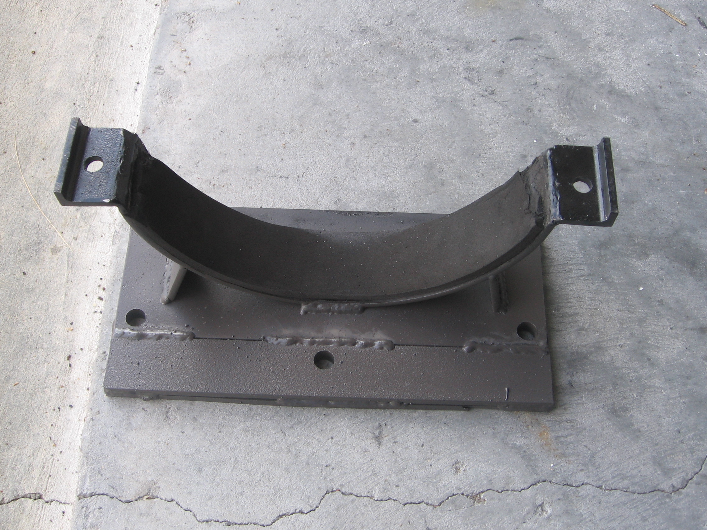
I located a transmission cross member here locally, however, they want
$350.00 for it and a couple of days to get it off the frame. I called
back twice to make sure he wasn't pricing a used transmission. You
paid $10. for yours? I recall telling you that I saw somebody selling
these things, believe that it was on eBay. See below. I found one
posting where they made their own.
Shopping results for transmission cross member,ford ranger
1973-1979 Ford Truck Manual Transmission ... $50.62 - eBay
Ford Ranger Transmission
Ford Ranger Transmission Description: Just try to find this cross
member for any less than $49.99. This cross member replaces the
existing one that hangs down and drags everything. It just bolts in
place up inside the frame rails. Very simple. I build mine out of 1/2"
thick CR steel, unlike the other companies that are making them out of
3/8" and even 1/4". Fits 1983-1997 trucks only!
Walt 9/15
I obtained a used a rear manual transmission crosssmember support from a 99
ranger at the junk yard for a reasonable price, I think it was $10. You may
or may not be able to duplicate this price.
Cheers,
Al Lococo
Where did you obtain the transmission cross member that you modified
to support the front end? Walt 9/8
Walt,
You are correct, I am using #10 wire and 20 amp plugs and receptacles
everywhere between the circuit breaker box and the charger. Things still
get warm at times.
Although opportunity charging will be more difficult, I believe 220 volt
charger is a good idea. With my supplier, at least, you need to ask for the
off board charger, I believe. Although I have no experience with this,
since I asked for the onboard charger and received the 120 volt version.
Cheers,
Al Lococo
I should add that the plan is 220V, 20 amps??
Do I recall you writing that you sensed a temp. problem in your
charging cord and were going to change from 12 to 10 gauge? Walt 9/8
Do I recall you writing that you sensed a temp. problem in your
charging cord and were going to change from 12 to 10 gauge? Walt 9/8
Walt,
This very interesting, but it draws 50 amps. My system is 30 amps. It might work without an upgrad if you don't do a lot of steering and maybe switch it off when you don't need it.
Very nice package. Naybe I should by one.
Cheers,
Al Lococo


